
PUMPA - SMART LEARNING
எங்கள் ஆசிரியர்களுடன் 1-ஆன்-1 ஆலோசனை நேரத்தைப் பெறுங்கள். டாப்பர் ஆவதற்கு நாங்கள் பயிற்சி அளிப்போம்
Book Free DemoIn the previous sections, we did activities to generate the induced current due to electromagnetic induction, which is usually very small. This principle is also used to produce large currents for use in homes and industry. For example, electric generators use this principle to generate electricity.
In this section, we shall discuss the construction and working of electric generators.
In an electric generator, mechanical energy is used to rotate a conductor in a magnetic field to generate electricity. It works on the principle of electromagnetic induction.
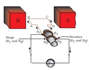
Illustration of the principle of electric generator
As shown in the figure, an electric generator contains a rotating rectangular coil ABCD located between the two poles of a permanent magnet. The two ends of this coil are attached to the two rings R1 and R2. The inner side of these rings is insulated. The two conducting brushes B1 and B2, are kept stationary and pressed separately on the rings R1 and R2, respectively. The two rings, R1 and R2, are internally connected to an axle.
The axle may be mechanically rotated from outside to rotate the coil inside the magnetic field. The outer ends of the two brushes are attached to the galvanometer to record the current flow in the given external circuit. When the axle connected to the two rings is rotated, the arm AB moves up (and the arm CD moves down) in the magnetic field created by the permanent magnet, let us say the coil ABCD is rotated clockwise in the arrangement as shown in the below figure.
By applying Fleming's right-hand rule, the induced currents start to flow in these arms along with AB and CD's directions. Thus, an induced current in the circuit flows in the direction of ABCD. If there are more numbers of turns in the coil, the current created in each turn adds up to provide a large current through the coil. This suggests that the current in the external circuit flows from B2 to B1.
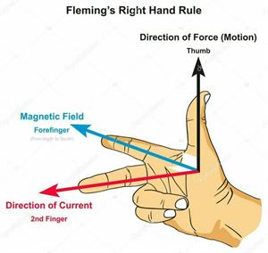
Fleming's right-hand rule
After half rotation, arm CD begins to move up, and AB moves down. Due to this, the directions of the induced currents in both the arms (AB and CD) change, providing rise to the net induced current in the direction DCBA. The current in the external circuit starts to flow from B1 to B2. Thus, after every half rotation, the polarity of the current in the respective arms changes. Such a current, which changes direction after equal intervals of time, is called an Alternating Current (abbreviated as AC). This device is called an AC generator.
A split-ring type commutator must be used to get a direct current (DC, which does not change its direction with time). With this arrangement, one brush is at all times in contact with the arm moving up in the field, while the other is in contact with the arm moving down. We have seen a split ring commutator working in the case of an electric motor. Thus, a unidirectional current is produced. The generator is thus called the DC generator.
The difference between the Direct and Alternating Currents (DC and AC) is that the direct current always flows in one direction, whereas the alternating current reverses its direction periodically. Most power stations constructed these days produce AC.
In India, the AC changes direction after every \(1/100\) second; that is, the frequency of AC is \(50\ Hz\). An important advantage of AC over DC is that electric power can be transmitted over long distances without much energy loss.
 Register for free to see more content